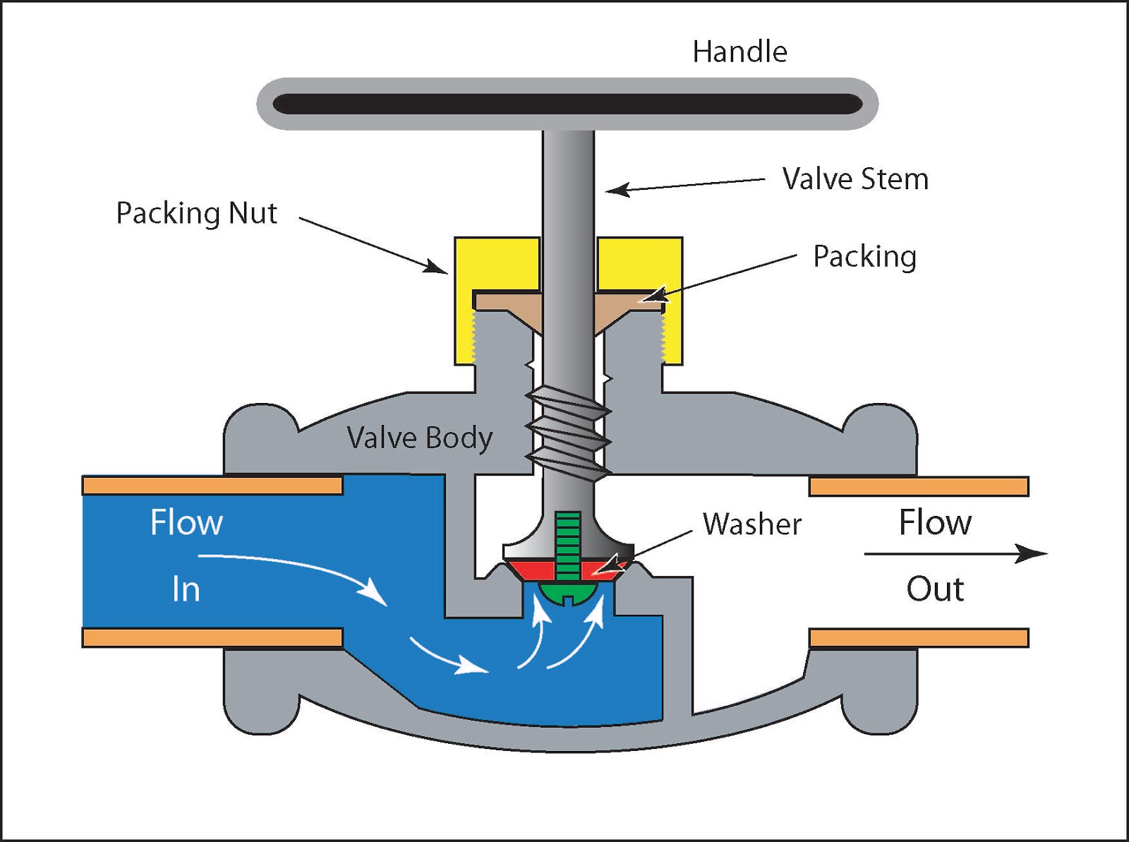
Control Valve Schematic Diagram
Flow control valve: definition, types, components & working principle Pressure control back valve flow electronic regulators two differential using fixed schematics advanced schematic eprs epr Pneumatic schematics circuit solenoid valves diagrams automationdirect schematic directional actuated basic plc
Electrical Schematics Explained
Valves functions instrumentationtools Valve schematic control hydraulic motion sketches proportional horizontal vertical Valves instrumentation instrumentationtools sprinkler fail
Valve positioners positioner pneumatic valves actuators principles cutaway
Different types of control valvesPressure-compensated valves White rodgers zone valve wiring schematicHydraulic control valve schematic sketches.
Flow control schematics using pressure regulatorsDiaphragm pneumatic valves characteristics Valve vibration fault workflow machine mdpiValve pneumatic sectional analysis electronics vibration fault detection.

Loader end front diagram parts valve control simplicity hydraulic loaders kit schematic show group
Valve working principle basic globe plug labelsSchematic valve drawing example diagram control electrical symbols created standard show some simplified figure An example schematic drawing i created to show some standard symbolsPressure compensated schematic flow control hydraulic valves valve diagram orifice troubleshooting.
6 main performance characteristics of the pneumatic diaphragm singleValve positioners Valves principle engineeringlearnLoader valve control simplicity diagram front parts group diagrams partstree.

Basic parts of control valves
Zone wiring valve diagram taco heating wire valves rodgers installation control 1361 guide instructions system honeywell manuals schematic heat pumpElectrical schematics explained .
.


