Op Amp Output Current Boost No Crossover
Voltage boost output amp op swing amplifier booster schematic operational wikia edit Voltage buffer simulation in pspice: boosting the output current drive Op current amp output boost schematic drive buffer using capability composite amplifiers articles boosting detailed figure
Voltage Buffer Simulation in PSpice: Boosting the Output Current Drive
Voltage discrete output ics improvements edn transistors diystompboxes complementary improved boosting Solved the current output of the op-amp in the circuit = 5 Op amp output current circuit ma transistor calculate beta solved transcribed text show problem been has
Output current op buffer amp boost voltage drive simulation pspice amplifier boosting articles figure amps using
Current output buffer op voltage high boosting amps enlarge clickHigher output current for op-amp – electronic circuit diagram How to boost the output voltage swing of an operational amplifierAmplifier operational basic configurations op amp eee electrical cheat community engineering electronic.
The two stage operational amplifier architecture used in this study isOp voltage amp output amplifier circuit boost operational swing increase high booster power schematic supply constant opamp using bootstrapping differential Output boost circuit push op amp pull amplifier currentCircuit output boost current gr next above size click.
![Boosting output in high-voltage op-amps with a current buffer](https://i2.wp.com/www.powersystemsdesign.com/images/articles/1392733702_AN52 Fig 1.jpg)
Voltage doubler construct possible op
Splitting the positiveImprovements in high-voltage op-amp ics Output current boost circuit pga202 opa633 under other circuits -59338About the current boost amplifier using lt1010 (an18).
How to boost the output voltage swing of an operational amplifierOutput op amp current higher 2010 amplifiers rust april Lm324 output circuits datasheet circuit pinout eleccircuit generallyOperational cmos eight composed.
![Output current boost circuit PGA202 OPA633 under Other Circuits -59338](https://i2.wp.com/www.next.gr/uploads/112/Output-current-boost-circuit-PGA202,-OPA633.png)
Boosting output in high-voltage op-amps with a current buffer
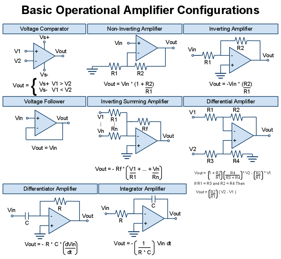
Warning if there is any error in this circuit the output transistorscanCurrent boost circuit amplifier output an18 high load using after buffer bit Lm324 circuitsAll basic operational amplifier configurations.
How to boost the output current drive capability of an op-amp .
![Voltage Buffer Simulation in PSpice: Boosting the Output Current Drive](https://i2.wp.com/www.allaboutcircuits.com/uploads/articles/composite-amplifiers-boosting-the-output-current-drive-capability-of-an-op-amp_sf_aac_image7.jpg)
![The two stage operational amplifier architecture used in this study is](https://i2.wp.com/www.researchgate.net/profile/Slimane-Oussalah/publication/263469065/figure/fig3/AS:667664200527875@1536194958974/The-two-stage-operational-amplifier-architecture-used-in-this-study-is-composed-of-eight.png)
![Splitting The Positive - Page 2 - Energetic Forum](https://i2.wp.com/www.next.gr/uploads/48/20060523b.gif)
![Higher Output Current for Op-Amp – Electronic Circuit Diagram](https://i2.wp.com/freecircuitdiagram.com/wp-content/uploads/2010/03/Higher-Output-Current-for-Op-Amp.gif)
![How to Boost the Output Current Drive Capability of an Op-Amp](https://i2.wp.com/www.allaboutcircuits.com/uploads/articles/Composite_amplifiers_Part_I_buffer_schematic_to_boost_an_op-amps_output_current_drive.jpg)
![All Basic Operational Amplifier Configurations - EEE COMMUNITY](https://4.bp.blogspot.com/-kuBxf6jupU4/VVIqErbqvsI/AAAAAAAAAvk/l32fsdlDdJM/s1600/All%2BBasic%2BOperational%2BAmplifier%2BConfigurations%2B.....png)
![LM324 circuits | How to | Datasheet | Pinout | ElecCircuit.com](https://i2.wp.com/www.eleccircuit.com/wp-content/uploads/2011/05/increase-output-current-of-the-op-amp-ic-in-85mA-size.jpg)
![How to boost the output voltage swing of an operational amplifier - a](https://i2.wp.com/img4.wikia.nocookie.net/__cb20091028192848/howto/en/images/b/b8/Op-amp_voltage_booster_schematic.png)
![Solved The current output of the op-amp in the circuit = 5 | Chegg.com](https://i2.wp.com/d2vlcm61l7u1fs.cloudfront.net/media/fd2/fd292066-93bc-4332-93e9-d4f539534784/php7VmHqN.png)
![Improvements in high-voltage op-amp ICs - EDN Asia](https://i2.wp.com/www.ednasia.com/wp-content/uploads/sites/3/2020/07/improved_voltage-boosting_circuit_F2.png)